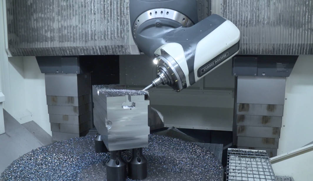
Surface roughness in CNC machining refers to the measure of the finely spaced, microscopic irregularities left on the surface of a part by the cutting tool during the manufacturing process. The most common metric used to quantify this texture is the Ra value (Roughness Average), which calculates the average deviation of a surface profile from its theoretical center line. In practical terms, an Ra value tells you how smooth or rough a machined part will be; lower Ra values indicate a smoother surface with microscopic peaks and valleys, while higher Ra values denote a rougher, more textured surface. Determining what Ra value you need depends entirely on the part’s intended application, as functional components like O-ring seals require exceptionally smooth finishes to prevent leaks, whereas structural brackets can function perfectly well with rougher, standard machined surfaces.
Understanding surface finish is critical for engineers and product designers because it directly impacts the mechanical performance, aesthetic appeal, and manufacturing cost of a component. When a cutting tool removes material, it inherently leaves behind tool marks. These micro-irregularities can affect how a part interacts with its environment, influencing factors such as friction, wear resistance, fatigue limit, and fluid retention. By accurately specifying the correct surface roughness on engineering drawings, designers communicate their exact requirements to the machine shop, ensuring the final product meets functional expectations without incurring unnecessary processing costs.
Understanding Surface Roughness Parameters: Ra, Rz, and RMS
To accurately communicate surface finish requirements, the manufacturing industry relies on standardized parameters. While there are dozens of ways to measure surface texture, a few key metrics dominate the CNC machining landscape. Understanding the distinctions between these measurements is vital for ensuring your manufacturing partner utilizes the correct inspection criteria for your specific application.
Ra (Roughness Average) Explained
Ra, or Roughness Average, is the universally accepted standard for specifying surface roughness in CNC machining. Measured in either micrometers (µm) for metric systems or microinches (µin) for imperial systems, Ra represents the arithmetic average of the absolute values of the profile height deviations from the mean line over a specified sampling length. Because it is an average, Ra is highly effective at providing a general overview of the surface texture. It easily filters out extreme, isolated peaks or valleys, giving a stable, repeatable measurement. However, this averaging nature is also its primary limitation; two surfaces with completely different microscopic profiles—one with deep, isolated scratches and another with uniform, shallow ripples—could technically yield the exact same Ra value. Therefore, while Ra is sufficient for over 90% of general machining applications, it may not be adequate for highly specialized sealing or bearing surfaces.
Rz (Mean Roughness Depth) and RMS (Root Mean Square)
When the limitations of Ra pose a risk to the part’s functionality, engineers turn to alternative parameters like Rz and RMS. Rz (Mean Roughness Depth) calculates the average distance between the highest peak and the lowest valley across five successive sampling lengths. Unlike Ra, Rz is highly sensitive to extreme irregularities. If a CNC machined part has a single deep scratch caused by chip dragging, the Rz value will spike, even if the Ra remains relatively low. This makes Rz the preferred callout for surfaces where a single deep defect could cause catastrophic failure, such as high-pressure hydraulic seals.
RMS (Root Mean Square), often denoted as Rq, is a mathematical variation of Ra. It calculates the square root of the mean of the squares of the surface profile deviations. Because it squares the values before averaging them, RMS gives more weight to larger deviations (higher peaks and deeper valleys) than Ra does. While RMS was heavily used in older American engineering drawings, it has largely been superseded by Ra in modern ISO and ASME standards. However, it is still occasionally encountered in legacy aerospace and defense prints.
Standard CNC Machining Ra Values and Their Applications
In the world of CNC milling and turning, standardizing surface roughness helps streamline the quotation and manufacturing process. Machinists typically categorize surface finishes into specific Ra tiers, each requiring different machining strategies, tooling, and time investments. Below is a detailed breakdown of the most common Ra values requested in custom part manufacturing.
| Metric Ra (µm) | Imperial Ra (µin) | Manufacturing Process | Typical Application |
|---|---|---|---|
| 3.2 µm | 125 µin | Standard high-speed CNC milling/turning | Non-visible structural parts, brackets, internal housings |
| 1.6 µm | 63 µin | Fine CNC machining with controlled feeds | Visible consumer parts, mating surfaces, tight tolerance fits |
| 0.8 µm | 32 µin | Precision grinding or very slow finishing passes | Static O-ring seals, bearing shafts, aesthetic faces |
| 0.4 µm | 16 µin | Lapping, honing, or hand polishing | Dynamic seals, optical components, fluid dynamics |
3.2 µm (125 µin) Ra: The Standard Commercial Finish
An Ra value of 3.2 µm (125 µin) is widely considered the default “as-machined” surface finish for most CNC machine shops. If you submit a 3D CAD model for a quote without specifying a surface roughness on an accompanying 2D drawing, this is the finish you will receive. At this roughness level, tool marks are distinctly visible to the naked eye, and you can easily feel the texture if you drag your fingernail across the surface. This finish is achieved using aggressive cutting parameters, prioritizing maximum material removal rates and shorter cycle times over aesthetics. It is highly cost-effective and is the ideal choice for functional brackets, internal enclosures, hidden structural components, and any application where visual perfection is not a strict requirement.
1.6 µm (63 µin) Ra: The Smooth Machined Finish
Stepping down to a 1.6 µm (63 µin) Ra requires the CNC machinist to be more deliberate with their finishing passes. Tool marks are still slightly visible, but they are much finer, and the surface feels significantly smoother to the touch. Achieving a 1.6 µm finish typically requires the use of a sharp finishing tool, increased spindle speeds, and reduced feed rates, which incrementally increases the machining time and cost. This Ra value is the industry standard for parts that require a good balance between cost and performance. It is commonly specified for mating surfaces where two parts are bolted together, general clearance fits, and exterior surfaces of industrial machinery that require a clean, professional appearance.
0.8 µm (32 µin) Ra: The Semi-Gloss Finish
Achieving an 0.8 µm (32 µin) Ra requires a high level of machining expertise and optimized equipment. At this level, the surface begins to take on a slight sheen, and tool marks become very difficult to detect without a magnifying loupe. To achieve this finish consistently, machinists must minimize machine vibrations, use premium carbide or diamond-tipped cutting tools, and employ high-quality cutting fluids. In many cases, specialized processes like cylindrical grinding or surface grinding are utilized to hit this specification. An Ra of 0.8 µm is typically reserved for highly functional precision parts. Common applications include static O-ring grooves (where the seal does not move), press fits, sliding friction surfaces, and high-end consumer products prior to anodizing or plating.
0.4 µm (16 µin) Ra: The Precision Polished Finish
An Ra value of 0.4 µm (16 µin) represents an exceptionally smooth, mirror-like finish that is virtually impossible to achieve through standard CNC milling or turning alone. Obtaining this level of microscopic smoothness requires secondary operations such as lapping, honing, centerless grinding, or meticulous manual polishing. Because of the intensive labor and specialized equipment required, specifying a 0.4 µm finish will exponentially increase the cost of your CNC machined parts. Therefore, it should only be called out when absolutely necessary. Applications that demand this stringent Ra value include dynamic seals (where an O-ring or lip seal is in constant motion against the metal), hydraulic cylinders, high-speed bearing journals, and mold cavities for plastic injection molding where the surface of the tool dictates the surface of the final plastic part.
Key Factors Affecting Surface Roughness in CNC Machining
Surface roughness is not a random occurrence; it is a highly controllable outcome dictated by the physics of the machining process. Machinists manipulate a variety of mechanical and environmental variables to achieve the specific Ra value requested by the engineer. Understanding these factors can help designers optimize their parts for better manufacturability.
Cutting Parameters: Speeds and Feeds
The most direct way a machinist controls surface roughness is by adjusting the speeds and feeds of the CNC machine. The feed rate (the speed at which the cutting tool advances through the material) is the primary driver of surface finish. A high feed rate creates deep, wide ridges, resulting in a high Ra value. Conversely, lowering the feed rate produces tighter, shallower ridges, drastically improving the surface finish. Cutting speed (the rotational speed of the spindle) also plays a crucial role. Higher spindle speeds tend to produce smoother finishes by reducing the likelihood of Built-Up Edge (BUE), a phenomenon where tiny bits of the workpiece material weld themselves to the cutting tool, subsequently tearing at the freshly machined surface. A skilled programmer will calculate the optimal ratio of high spindle speed to low feed rate during the final finishing pass to achieve a low Ra value.
Cutting Tool Geometry and Wear
The physical characteristics of the cutting tool leave a direct imprint on the workpiece. The nose radius of the cutting insert is exceptionally important. A larger nose radius spreads the cutting force over a wider area, creating a smoother, shallower scalloped pattern on the part’s surface, which lowers the Ra value. However, a larger nose radius also increases radial tool pressure, which can cause chatter (vibration) if the part is thin or the setup is not rigid. Additionally, tool wear is an unavoidable reality in machining. As a sharp endmill or turning insert becomes dull, it begins to rub and tear the material rather than shearing it cleanly. This friction generates excess heat and leaves a ragged, highly textured surface. Maintaining strict tool-change schedules is essential for shops aiming to hold tight surface finish tolerances over large production runs.
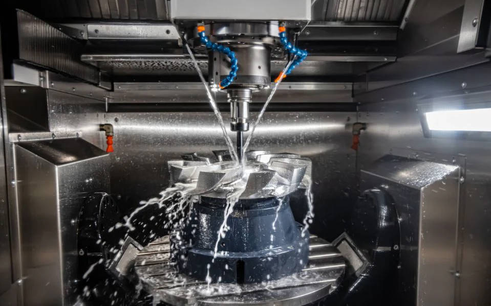
Material Properties and Coolant Usage
The inherent properties of the raw material dramatically influence the achievable surface finish. Harder metals, such as stainless steel and titanium, generally take a better surface finish than soft, gummy materials like pure aluminum or low-carbon steel. Soft materials tend to tear and stick to the cutting tool, making it difficult to achieve a pristine surface without highly specialized, ultra-sharp tooling. Furthermore, the strategic application of coolant and lubricants is vital. High-pressure coolant flushes metal chips away from the cutting zone. If chips are not evacuated efficiently, the cutting tool will drag them back across the newly machined surface, causing deep scratches that ruin the Ra value. Lubricants also reduce the friction between the tool and the workpiece, minimizing heat generation and preventing the aforementioned Built-Up Edge.
How to Measure Surface Roughness
Validating that a part meets the specified Ra value requires precise metrology equipment. The most common tool used in machine shops is the contact profilometer. This device utilizes an ultra-fine diamond stylus that physically drags across the surface of the machined part. As the stylus traverses the microscopic peaks and valleys, a transducer converts these vertical mechanical movements into an electrical signal, generating a precise numerical Ra reading and a graphical surface profile on a digital display. Profilometers are highly accurate, portable, and relatively inexpensive, making them the standard for shop-floor inspections.
However, contact profilometers have limitations; they can scratch highly sensitive parts, and they cannot easily measure the inside of deep, narrow bores. For advanced applications, non-contact optical metrology is used. Devices such as white light interferometers and confocal microscopes use light waves to create high-resolution 3D topographical maps of the surface. While optical scanners are significantly more expensive and generally confined to climate-controlled quality labs, they provide incredibly comprehensive data, measuring not just Ra and Rz, but complex 3D areal surface texture parameters (Sa, Sz) without ever touching the part.
The Cost Implications of Specifying Tight Ra Values
One of the most critical lessons in mechanical design is understanding the exponential relationship between surface roughness and manufacturing cost. As the Ra value decreases (meaning the surface gets smoother), the cost to produce that surface increases dramatically. Specifying a standard 3.2 µm Ra finish allows the machinist to run the machine at maximum efficiency. If a designer unnecessarily tightens that specification to a 0.8 µm Ra, the machinist must add extra tool changes, slow down the feed rates significantly, and perhaps run multiple spring passes to hit the target. This increases the machine cycle time, which directly inflates the price of the part.
When you cross the threshold into finishes of 0.4 µm Ra or finer, costs skyrocket. The part must be removed from the CNC machine and transitioned to secondary processes like grinding or manual polishing. This introduces additional labor hours, requires different specialized machinery, and increases the risk of scrapping the part during handling. A common rule of thumb in design for manufacturability (DFM) is that improving a surface finish from 3.2 µm to 0.4 µm can increase the cost of that specific feature by 400% or more. Therefore, engineers must rigorously evaluate the functional requirements of their components to avoid over-engineering the surface finish and needlessly driving up production budgets.
How to Choose the Right Ra Value for Your CNC Parts
Choosing the correct Ra value requires a pragmatic balance between the part’s functional necessities and your project’s budget constraints. The best practice is to always specify the roughest possible surface finish that still allows the part to perform its intended function flawlessly. If a part is purely structural and will be hidden inside a machine chassis, rely on the standard 3.2 µm (125 µin) Ra. There is zero return on investment for polishing an internal bracket.
When dealing with mating parts, consider the type of fit. Standard clearance fits function perfectly well at 1.6 µm (63 µin) Ra. If the part involves a press fit or sliding friction, you will need to step down to a 0.8 µm (32 µin) Ra to prevent excessive wear and galling. Finally, reserve the ultra-smooth 0.4 µm (16 µin) Ra requirements exclusively for mission-critical features, such as dynamic fluid seals, optical housings, or high-friction rotary bearing surfaces. When creating your engineering drawings, use specific surface finish callouts (the checkmark symbol) only on the specific faces, diameters, or bores that actually require a tight finish, rather than applying a blanket tight Ra tolerance to the entire part block. This targeted approach ensures maximum performance while keeping your CNC machining costs highly competitive.