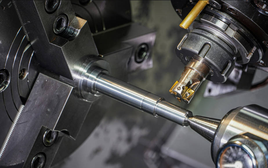
CNC turning is a subtractive manufacturing process where a bar of material, the workpiece, is held in a chuck and rotated at high speed while a cutting tool is fed into it to remove material and create a final cylindrical part. This process, controlled by a computer via G-code, allows for the precise and repeatable production of components with complex external and internal features. From simple shafts and pins to intricate aerospace and medical device components, CNC turning is a cornerstone of modern manufacturing.
Understanding how this technology transforms a raw block of metal or plastic into a precision-engineered part is crucial for engineers, designers, and hobbyists alike. This comprehensive guide will walk you through the entire CNC turning process, from the initial digital design to the final inspected component. We will explore the key components of a CNC lathe, detail each step of the workflow, and examine the various operations that can be performed.
What is CNC Turning? The Fundamentals Explained
At its core, CNC turning is the modern, automated version of traditional lathing. The term “CNC” stands for Computer Numerical Control, which signifies that the machine’s movements are dictated by a pre-programmed computer code rather than a manual operator turning cranks and levers. The fundamental action involves rotating the workpiece, while a stationary (or moving on specific axes) cutting tool shapes it. Think of it like a highly advanced potter’s wheel, but instead of clay being shaped by hands, a metal bar is precisely sculpted by a cutting tool.
The Core Principle: A Modern Take on the Lathe
The defining characteristic of turning is that the workpiece rotates while the cutting tool moves linearly. The tool is mounted on a turret, which can move along two primary axes: the Z-axis (parallel to the workpiece’s axis of rotation, controlling length) and the X-axis (perpendicular to the axis of rotation, controlling diameter). By coordinating the movement along these axes, the machine can create a wide variety of shapes, including tapers, contours, steps, and threads, all with incredible accuracy and surface finish.
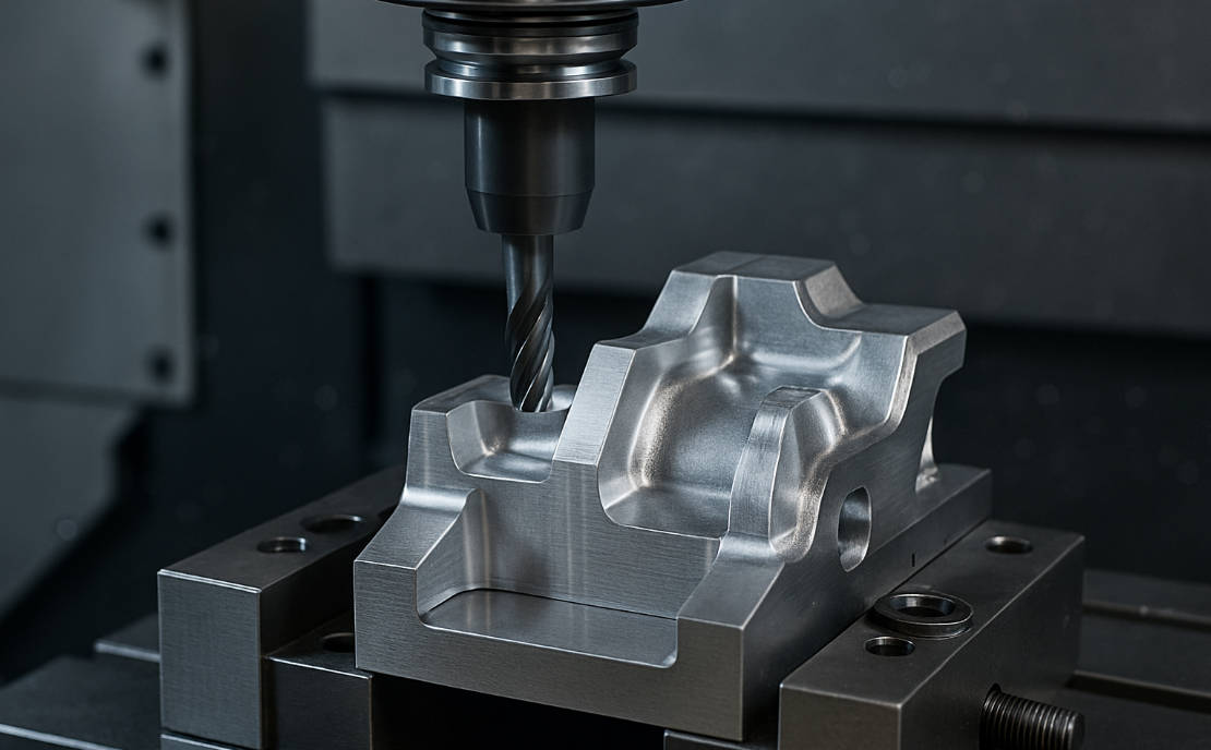
CNC Turning vs. CNC Milling: What’s the Difference?
A common point of confusion is the difference between CNC turning and CNC milling. While both are subtractive manufacturing processes controlled by computers, their fundamental mechanics are opposite. Understanding this distinction is key to selecting the right process for a given part design.
| Feature | CNC Turning (Lathe) | CNC Milling (Mill) |
|---|---|---|
| Primary Action | The workpiece rotates at high speed. | The cutting tool rotates at high speed. |
| Tool/Workpiece Motion | The cutting tool moves linearly into the rotating workpiece. | The workpiece is held stationary (or moves on a table) as the rotating tool moves across it. |
| Part Geometry | Best for cylindrical or conical parts (shafts, pins, rings, nozzles). | Best for prismatic or squarer parts with flat surfaces, pockets, and holes (enclosures, brackets, molds). |
| Machine Axes | Typically 2-axis (X, Z), but can have more with live tooling. | Typically 3-axis (X, Y, Z), with 4- and 5-axis machines for complex geometries. |
The Anatomy of a CNC Lathe: Understanding the Key Components
A CNC turning center, or lathe, is a complex machine with several critical components working in unison. Familiarity with these parts helps to understand how the entire process functions.
| Component | Function |
|---|---|
| Headstock | The main body of the lathe that houses the primary spindle and the drive mechanism (motor and gears) that rotates it. |
| Spindle | The rotating shaft that holds the workpiece. Its speed (RPM) is computer-controlled and is a critical parameter in the turning process. |
| Chuck / Collet | A specialized clamp attached to the spindle that grips the workpiece securely. Chucks typically have 3 or 4 jaws, while collets offer a more precise grip for smaller diameter stock. |
| Tailstock | Positioned opposite the headstock, it provides support to the other end of a long workpiece, preventing it from deflecting or vibrating during machining. |
| Bed | The rigid, foundational base of the lathe upon which all other components are mounted. It provides stability and absorbs vibrations. |
| Carriage / Cross-slide | The assembly that moves along the Z-axis (carriage) and X-axis (cross-slide), carrying the tool turret. |
| Tool Turret | An indexable holder that houses multiple cutting tools. The computer can rotate the turret to bring the required tool into the cutting position, allowing for multiple operations without a manual tool change. |
| CNC Controller | The “brain” of the machine. It reads the G-code program and translates it into electrical signals that control the motors for the spindle, axes, turret, and coolant pump. |
The CNC Turning Process: From Digital Design to Physical Part
The journey from an idea to a finished turned component follows a structured, multi-stage workflow. Each step is critical to ensuring the final part meets the required specifications for accuracy, finish, and functionality.
Step 1: The Blueprint – CAD Design
The process begins with a digital design. Using Computer-Aided Design (CAD) software like SolidWorks, Autodesk Inventor, or Fusion 360, an engineer or designer creates a 2D drawing or a 3D model of the part. This digital blueprint contains all the necessary geometric information, including diameters, lengths, contours, and tolerances. The CAD model serves as the definitive source of truth for the part’s intended shape and size.
Step 2: The Instructions – CAM and G-Code Generation
A 3D model alone cannot be read by a CNC machine. The next step is to use Computer-Aided Manufacturing (CAM) software to translate the CAD model into machining instructions. The CAM software helps the programmer define the machining strategy, including:
- Selecting the appropriate cutting tools for each feature.
- Setting cutting parameters like spindle speed (RPM), feed rate (how fast the tool moves), and depth of cut.
- Simulating the entire machining process to detect any potential collisions or errors.
Once the strategy is set, the CAM software outputs a text file containing the program. This program is written in a language called G-code (and M-code), which is the standard numerical control language that tells the CNC machine exactly what to do. Each line of code is a specific command, such as G01 X1.5 Z-2.0 F0.005; which instructs the machine to move the tool in a straight line to a specific coordinate at a specific feed rate.
Step 3: The Preparation – Machine Setup
With the G-code program ready, a skilled machinist prepares the CNC lathe. This is a critical hands-on step that involves several tasks:
- Loading the Program: The G-code file is transferred to the CNC controller, typically via USB, Ethernet, or a wireless connection.
- Installing Tooling: The machinist mounts the required cutting tools (e.g., roughing tools, finishing tools, drills, threading inserts) into the correct positions on the tool turret.
- Setting Tool Offsets: Each tool’s exact position and length must be precisely measured and input into the controller. This process, known as “touching off,” ensures the machine knows exactly where the tip of each tool is, which is crucial for maintaining dimensional accuracy.
- Preparing Coolant: The machinist ensures the coolant system is full and directed properly. Coolant is essential for lubricating the cutting action, cooling the tool and workpiece, and flushing away chips.
Step 4: The Foundation – Securing the Workpiece
A piece of raw material (stock), typically a round bar of metal or plastic, is cut to a rough length. This workpiece is then securely clamped into the machine’s chuck or collet. A secure grip is paramount; if the workpiece moves during the high-speed rotation, it can lead to inaccurate dimensions, poor surface finish, or a dangerous failure.
Step 5: The Action – Executing the Machining Program
With the setup complete, the operator closes the safety doors and starts the program. The machine comes to life, executing the G-code line by line:
- The spindle spins the workpiece up to the programmed speed.
- The tool turret indexes to the first required tool.
- The carriage and cross-slide move the tool to the starting position.
- The tool engages with the rotating material, cutting away chips as it follows the programmed path.
- The machine automatically changes tools as needed to perform different operations like drilling, threading, or finishing.
The machinist monitors the process, listening for unusual sounds, watching for chip buildup, and making minor adjustments to feeds and speeds if necessary to optimize the cut.
Step 6: The Verification – Quality Control and Inspection
After the program finishes and the machine stops, the operator removes the completed part. It’s not finished yet, however. The part undergoes a thorough inspection to ensure it meets the specifications laid out in the original CAD drawing. This is done using precision measuring instruments such as:
- Calipers and Micrometers: For measuring external and internal diameters and lengths.
- Go/No-Go Gauges: For quickly checking if threaded or bored holes are within tolerance.
- Coordinate Measuring Machine (CMM): For highly complex parts, a CMM can be used to automatically measure hundreds of points and compare them against the CAD model.
Only after passing this quality control check is the part considered complete. Any required post-processing steps, like deburring, polishing, or anodizing, can then be performed.
What are the Common CNC Turning Operations?
The versatility of CNC turning comes from the wide range of cutting operations that can be performed by using different tools and toolpaths. Here are some of the most common ones:
- Facing: Creating a flat, smooth surface on the end of the workpiece by feeding the tool from the center outwards along the X-axis.
- Turning: The primary operation of removing material from the outer diameter of the workpiece. This can be rough turning (high material removal rate) or finish turning (slower, more precise cut for a smooth surface).
- Grooving and Parting: Plunging a specific tool into the workpiece to create a groove of a certain depth. A special type of grooving, called parting or cut-off, is used to slice a finished part from the end of the bar stock.
- Threading: Cutting helical threads onto the external or internal diameter of the part, used for creating screws, bolts, and nuts.
- Drilling and Boring: Creating or enlarging a hole in the center of the workpiece. Drilling uses a standard drill bit, while boring uses a single-point tool to enlarge an existing hole to a very precise diameter.
- Knurling: Pressing a patterned tool against the workpiece to create a textured, grippable surface, often seen on knobs and handles.
What Materials Are Suitable for CNC Turning?
CNC turning is compatible with a vast array of materials, making it a flexible solution for many industries. The choice of material depends on the application’s requirements for strength, weight, corrosion resistance, and cost. Common materials include:
- Metals: Aluminum, Stainless Steel, Carbon Steel, Brass, Copper, Titanium, and various alloys.
- Plastics: ABS, Polycarbonate, Nylon, PEEK, Delrin (Acetal), and Acrylic.
- Exotics: Inconel, Monel, and other superalloys for high-performance applications.
Why Choose CNC Turning? Key Advantages and Applications
CNC turning is a dominant force in manufacturing for several compelling reasons, making it the preferred method for producing a wide range of parts across numerous industries.
The Benefits: Precision, Speed, and Complexity
The primary advantages of CNC turning include:
- High Precision and Repeatability: Computer control ensures that every part produced is virtually identical, with tolerances as tight as ±0.0005 inches (0.013 mm) or better.
- Speed and Efficiency: Once programmed, a CNC lathe can produce parts much faster and more continuously than a manual lathe, making it ideal for both prototyping and high-volume production.
- Complex Geometries: CNC machines can execute coordinated movements that would be impossible for a human operator, allowing for the creation of complex contours and features.
- Excellent Surface Finish: With the right tooling and parameters, CNC turning can produce parts with a very smooth and aesthetically pleasing surface finish, often eliminating the need for secondary polishing operations.
Common Industrial Applications
Due to these benefits, CNC turned components are found everywhere. Key industries that rely heavily on this process include:
- Aerospace: High-precision components like engine shafts, turbine blades, and fittings.
- Automotive: Parts for engines and transmissions, such as pistons, valves, and driveshafts.
- Medical: Surgical instruments, custom orthopedic implants, and components for medical devices.
- Electronics: Connectors, housings, and small shafts for various electronic devices.
- Oil & Gas: Valves, fittings, and downhole drilling components that must withstand harsh environments.
Conclusion: The Power and Precision of CNC Turning
CNC turning is a sophisticated yet elegantly simple process at its heart. By rotating a workpiece and precisely guiding a cutting tool, it transforms raw material into functional, highly accurate components that power our world. The step-by-step process—from a digital CAD model to a physically inspected part—is a testament to the integration of design, software, and advanced machinery. Whether for a single prototype or a million-part production run, understanding how CNC turning works reveals a core pillar of modern engineering and manufacturing.
Table of Contents
- What is CNC Turning? The Fundamentals Explained
- The Core Principle: A Modern Take on the Lathe
- CNC Turning vs. CNC Milling: What’s the Difference?
- The Anatomy of a CNC Lathe: Understanding the Key Components
- The CNC Turning Process: From Digital Design to Physical Part
- Step 1: The Blueprint – CAD Design
- Step 2: The Instructions – CAM and G-Code Generation
- Step 3: The Preparation – Machine Setup
- Step 4: The Foundation – Securing the Workpiece
- Step 5: The Action – Executing the Machining Program
- Step 6: The Verification – Quality Control and Inspection
- What are the Common CNC Turning Operations?
- What Materials Are Suitable for CNC Turning?
- Why Choose CNC Turning? Key Advantages and Applications
- The Benefits: Precision, Speed, and Complexity
- Common Industrial Applications
- Conclusion: The Power and Precision of CNC Turning
Main Keywords: CNC turning work, CNC turning process, CNC lathe
Long-tail Keywords: how does CNC turning work step-by-step, what is the process of CNC turning, CNC turning explained, CNC turning center operations, step-by-step guide to CNC turning, CNC turning from design to part, understanding CNC turning workflow, components of a CNC lathe, what is CNC turning used for
Synonyms: CNC lathing, turning process, subtractive manufacturing, computer numerical control turning, machining process
Interrogative Pronouns: What, How, Why