Table of Contents
- 1. Introduction
- 2. What Are CNC Machining Tolerances?
- 3. Standard Tolerances
- 4. Precision Tolerances
- 5. Standard vs. Precision Tolerances: Key Differences
- 6. Common Questions About CNC Machining Tolerances
- 7. How to Specify Tolerances for CNC Machining
- 8. Industry Standards for CNC Tolerances
- 9. Challenges and Considerations in Achieving Tolerances
- 10. Conclusion
- 11. FAQs
1. Introduction
In the world of modern manufacturing, Computer Numerical Control (CNC) machining stands as a pillar of precision, transforming digital designs into physical components with remarkable accuracy. From aerospace components to medical implants, the ability to produce complex parts consistently is paramount. At the heart of this consistency and reliability lies a critical concept: machining tolerances.
Tolerances are more than just numbers on a technical drawing; they are the language of precision, defining the acceptable range of variation for a part’s dimensions to ensure it functions as intended. Misunderstanding or misapplying tolerances can lead to parts that don’t fit, assemblies that fail, and budgets that spiral out of control.
This comprehensive guide aims to demystify CNC machining tolerances, specifically addressing the crucial differences between standard and precision tolerances. It is written for manufacturers, engineers, designers, and anyone seeking CNC machining services who needs to make informed decisions about their projects. By understanding the trade-offs between cost, speed, and accuracy, you can optimize your designs, communicate effectively with service providers, and ultimately create successful, high-quality products.
2. What Are CNC Machining Tolerances?
In an ideal world, every manufactured part would perfectly match its digital model down to the last atom. In reality, the manufacturing process—even one as precise as CNC machining—always involves a minute degree of variation. A CNC machining tolerance is the permissible limit of variation in a physical dimension of a part. It dictates how much a finished component can deviate from its nominal (or ideal) dimension while still being considered acceptable.
Tolerances are fundamental to manufacturing for several key reasons:
- Interchangeability: They ensure that parts produced in different batches or even by different manufacturers can be used interchangeably in an assembly.
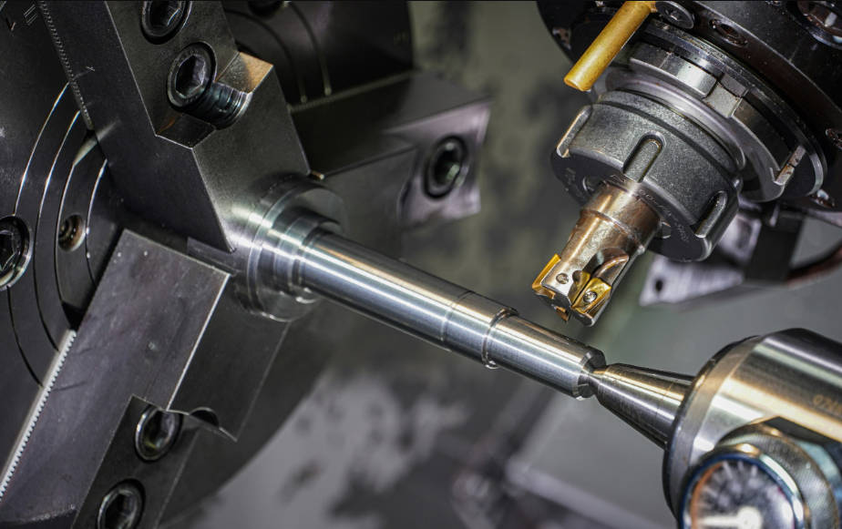
- Functionality: Tolerances guarantee that mating parts will fit and function correctly together—for example, ensuring a shaft can rotate freely within a bearing without being too loose or too tight.
- Performance: In high-performance applications, precise tolerances are critical for efficiency, safety, and reliability.
- Cost Control: They provide a realistic framework for manufacturing, acknowledging that achieving absolute perfection is impossible and prohibitively expensive.
To understand tolerances, you must be familiar with three key terms:
- Nominal Dimension: This is the ideal or target size specified in the design drawing. For example, a shaft’s nominal diameter might be 25 mm.
- Upper and Lower Limits: These are the maximum and minimum sizes the feature can be. For the 25 mm shaft, the upper limit might be 25.01 mm, and the lower limit might be 24.99 mm.
- Tolerance Range: This is the total amount of variation allowed, calculated as the difference between the upper and lower limits. In the example above, the tolerance range is 0.02 mm. This is often expressed on drawings as $25 \pm 0.01 \text{ mm}$.
Essentially, tolerances create an “acceptance window.” As long as the final measured dimension falls within this window, the part passes inspection.
3. Standard Tolerances
Standard tolerances, often referred to as commercial tolerances, represent the default level of accuracy that a capable CNC machine shop can achieve without requiring special setups, tooling, or processes. They are the baseline for general-purpose machining and offer the most balanced combination of precision, speed, and cost.
A common industry benchmark for standard tolerance in CNC machining is approximately ±0.005 inches (or ±0.127 mm). However, this can vary based on the machine shop, the material being used, and the specific dimension. Many shops will specify their standard tolerance range in a general note on their drawings, often referencing a standard like ISO 2768-m (medium).
Typical Applications
Standard tolerances are perfectly suitable for a vast range of applications where the absolute highest level of precision is not a functional requirement. These include:
- General-purpose mechanical parts like brackets, housings, and enclosures.
- Non-critical components that do not mate with other high-precision parts.
- Prototypes intended for form and fit checks.
- Structural components where slight dimensional variations do not impact performance.
- Jigs and fixtures used in assembly processes.
Advantages
- Cost-Effective: This is the primary benefit. Machining to standard tolerances requires less machine time, standard tooling, simpler quality control checks, and results in a lower scrap rate. This directly translates to a lower cost per part.
- Faster Production: Because machining parameters (like feed rates and cutting speeds) can be optimized for speed rather than ultimate accuracy, lead times are significantly shorter.
- Wider Range of Suppliers: Most CNC shops are equipped to consistently meet standard tolerances, giving you more options when choosing a manufacturing partner.
Limitations
The main limitation of standard tolerances is their unsuitability for applications where precision is critical. For parts in a high-speed rotating assembly, medical devices, or optical instruments, the variation allowed by standard tolerances could lead to poor performance, excessive wear, or complete functional failure.
4. Precision Tolerances
Precision tolerances, also known as tight tolerances, represent a significant step up in accuracy from standard tolerances. Achieving them requires more advanced machinery, specialized tooling, highly controlled processes, and often a climate-controlled environment. These are not the default; they must be explicitly specified for critical features where minimal variation is essential for function and performance.
Precision tolerance ranges typically fall between ±0.001″ (±0.025 mm) and ±0.0005″ (±0.013 mm), though even tighter tolerances down to ±0.0001″ (±0.0025 mm) are possible with specialized equipment and secondary processes like grinding or lapping.
Applications
Precision tolerances are mandated in industries where failure is not an option and performance is measured in microns.
- Aerospace: Components for jet engines, missile guidance systems, and landing gear where fit and material integrity are critical for safety.
- Medical: Surgical instruments, prosthetic joints, and implantable devices (e.g., pacemakers) that must meet stringent functional and biocompatibility standards.
- Automotive: High-performance engine parts like pistons and cylinders, fuel injectors, and transmission components where efficiency and longevity are key.
- Electronics & Optics: Components for semiconductor manufacturing, lens mounts, and fiber-optic connectors where precise alignment is crucial.
Advantages
- High Accuracy and Repeatability: Guarantees that parts will fit and perform exactly as designed, every time.
- Improved Performance: Enables higher efficiency, reduced vibration, and longer service life in critical assemblies.
- Enables Complex Designs: Makes it possible to design and build sophisticated mechanisms where multiple components must interact flawlessly in a small space.
Limitations
- Higher Costs: The cost of achieving tight tolerances increases exponentially. This is due to the need for higher-end machines, more expensive cutting tools, slower machining speeds, extensive in-process inspection, and a higher potential for scrapped parts.
- Longer Lead Times: Slower machining cycles and more rigorous quality assurance processes mean that producing parts with precision tolerances takes significantly longer.
- Material and Design Constraints: Not all materials or part designs are suitable for holding extremely tight tolerances.
5. Standard vs. Precision Tolerances: Key Differences
Choosing between standard and precision tolerances is a critical design decision that directly impacts a project’s cost, timeline, and final performance. The fundamental rule is to use standard tolerances wherever possible and reserve precision tolerances only for features that absolutely require them.
Comparison Table: Standard vs. Precision
| Feature | Standard Tolerances | Precision Tolerances |
|---|---|---|
| Typical Range | ±0.005″ (±0.127 mm) | ±0.001″ to ±0.0001″ (±0.025 mm to ±0.0025 mm) |
| Accuracy & Fit | Good for general fit and function. | Excellent for high-performance, interference, or clearance fits. |
| Cost | Lower (Baseline) | Significantly Higher (Can be 2x to 10x+ higher) |
| Lead Time | Faster | Slower |
| Typical Applications | Brackets, enclosures, prototypes, non-critical parts. | Aerospace, medical implants, engine components, optics. |
| Required Machinery | Standard 3-axis or 5-axis CNC machines. | High-end, well-maintained CNC machines, CMM for inspection. |
| Inspection Process | Calipers, micrometers. | CMM, laser scanners, optical comparators. |
| Design Flexibility | More forgiving of complex geometries. | Requires careful design for manufacturability (DFM). |
Factors Influencing the Choice
When deciding on the right tolerance, consider these factors:
- Part Function: What does this part do? Does it move? Does it mate with another part? If it’s a static cover panel, standard tolerance is likely fine. If it’s a piston in a cylinder, precision tolerance is required.
- Mating Parts: The most important consideration. If two parts must press together (an interference fit) or slide with a specific amount of clearance, their tolerances are interdependent and often need to be precise.
- Operating Environment: Will the part be exposed to extreme temperatures? Thermal expansion and contraction can affect how parts fit, sometimes necessitating tighter initial tolerances.
- Cost vs. Performance: This is the ultimate trade-off. Always ask: Is the performance gain from a tighter tolerance worth the significant increase in cost?
Real-World Examples
- When to Use Standard: Imagine designing an aluminum project box for an electronics board. The mounting holes for the board need to be located accurately, but a standard tolerance of ±0.005″ provides more than enough play. The overall dimensions of the box can also have a standard tolerance, as a slight variation won’t affect its function.
- When to Use Precision: Now consider the design of a gearbox. The shafts must be machined to a very tight tolerance (e.g., ±0.0005″) to fit perfectly with the bearings. The locations of the gear shafts relative to each other also require a tight positional tolerance to ensure smooth and efficient power transmission. Using standard tolerances here would result in a noisy, inefficient gearbox that would fail prematurely.
6. Common Questions About CNC Machining Tolerances
How do I choose the right tolerance for my project?
Start with the most lenient tolerance possible that still allows your part to function correctly. Analyze each feature of your part. Identify critical surfaces, holes, and features that interact with other components. These are candidates for tighter tolerances. For all other non-critical features, apply a general standard tolerance. This practice, known as functional tolerancing, is the most cost-effective approach.
What factors affect achievable tolerances?
Several factors combine to determine the tightest possible tolerance:
- Material: Stable materials like steel, stainless steel, and titanium hold tolerances better than soft materials like plastics (e.g., Delrin, Nylon), which can deform under cutting pressure or expand/contract significantly with temperature changes.
- Machine: The quality, rigidity, and calibration of the CNC machine are paramount. A high-end, thermally-stable 5-axis mill can achieve much tighter tolerances than a standard 3-axis machine.
- Part Design: Geometry plays a huge role. Features like long, thin walls are prone to vibration and warping, making them difficult to machine to a tight tolerance. Deep pockets can cause tool deflection, and sharp internal corners are impossible to machine perfectly (they will always have a radius from the tool).
- Tooling: The type, sharpness, and material of the cutting tool, as well as the tool holder’s rigidity, all impact the final part accuracy.
Can tighter tolerances be achieved on any material?
No. Materials with low hardness and poor thermal stability, such as plastics and some aluminums, are challenging to machine to extremely high precision. The heat generated during cutting can cause the material to expand, and it may not return to its original dimension perfectly. Harder, more stable materials like tool steel, stainless steel, and ceramics are much better suited for high-precision applications.
How do tolerances impact cost and production time?
The relationship is exponential. Moving from a standard tolerance (e.g., ±0.005″) to a precision one (e.g., ±0.001″) might double the cost. Moving to a very tight tolerance (e.g., ±0.0002″) could increase the cost by 5 to 10 times. This is because tighter tolerances demand slower cutting speeds, lighter passes, more expensive tooling, in-process checks, and more advanced (and costly) inspection equipment. Each of these steps adds time and expense.
What happens if tolerances are not met?
If a part is machined “out of tolerance,” it fails the quality inspection. The consequences can range from minor to catastrophic:
- Scrap: The part is discarded, wasting material, machine time, and money.
- Rework: If possible, the part may be re-machined to bring it into tolerance, adding cost and time.
- Assembly Failure: The part may not fit with its mating components, halting the entire production line.
- Performance Degradation: The final product may function poorly, wear out quickly, or be inefficient.
- Catastrophic Failure: In critical applications like aerospace or medical, a part failing due to incorrect tolerances could have life-threatening consequences.
7. How to Specify Tolerances for CNC Machining
Clearly and correctly communicating your tolerance requirements is just as important as designing them. Ambiguity on a technical drawing can lead to costly mistakes.
Best Practices for Technical Drawings
- Use a Title Block for General Tolerances: Specify a standard tolerance for all dimensions unless otherwise noted. For example, “ALL DIMENSIONS ±0.1 mm UNLESS OTHERWISE SPECIFIED. FOLLOW ISO 2768-m.” This cleans up the drawing and saves you from having to tolerance every single feature.
- Call Out Critical Tolerances Directly: For any feature that needs a tolerance tighter than the general note, specify it directly on that dimension.
- Use Geometric Dimensioning and Tolerancing (GD&T): For complex parts, GD&T is a universal language that goes beyond simple plus/minus tolerances. It allows you to specify tolerances for flatness, straightness, position, profile, and more, providing much more precise control over the part’s form and function.
- Provide Both 2D Drawings and 3D Models: The 3D CAD model defines the nominal geometry of the part. The 2D technical drawing is the governing document that officially defines the tolerances, materials, finishes, and other manufacturing requirements.
Tips for Optimizing Design for Cost and Manufacturability
- Question Every Tight Tolerance: For every dimension with a precision tolerance, ask yourself, “Is this absolutely necessary for the part to function?” If the answer is uncertain, it probably isn’t.
- Avoid Sharp Internal Corners: CNC tools are round, so they create a radius in every internal corner. Specifying a sharp corner requires a secondary, more expensive process like EDM. Always design with a corner radius that is larger than the tool radius if possible.
- Communicate Early and Often: Talk to your CNC service provider during the design phase. They can provide invaluable feedback on your design’s manufacturability and help you find the most cost-effective way to achieve your functional goals.
8. Industry Standards for CNC Tolerances
To ensure consistency and clear communication across the manufacturing industry, several standards have been developed to define general tolerances.
ISO 2768
The International Organization for Standardization (ISO) provides ISO 2768 to simplify technical drawings by defining general tolerances for linear and angular dimensions. It specifies four tolerance classes:
- f (fine)
- m (medium)
- c (coarse)
- v (very coarse)
ISO 2768-m is the most commonly used standard for general machining. By simply stating “ISO 2768-m” in the drawing’s title block, a designer can apply a well-defined set of standard tolerances to all dimensions without having to specify them individually.
ASME Y14.5
The American Society of Mechanical Engineers (ASME) Y14.5 is the authoritative standard for Geometric Dimensioning and Tolerancing (GD&T) in the United States. Unlike ISO 2768, which provides tables of values, ASME Y14.5 is a symbolic language that defines how to specify and interpret tolerances related to a part’s form, profile, orientation, location, and runout. It is the standard for industries that require precise control over complex geometries, such as aerospace, defense, and automotive.
Adhering to these standards ensures that the design intent is communicated unambiguously, regardless of where the part is manufactured. It is the foundation of modern quality control.
9. Challenges and Considerations in Achieving Tolerances
Even with the best machines and skilled operators, achieving tight tolerances is a complex challenge influenced by many variables.
- Material Properties: As discussed, thermal expansion is a major enemy of precision. A part machined in a 68°F (20°C) environment might be out of tolerance if inspected at 75°F. Different materials expand at different rates, a property known as the Coefficient of Thermal Expansion (CTE), which must be accounted for in high-precision work.
- Machine Capabilities: Not all CNC machines are created equal. Factors like spindle runout, machine rigidity, and the accuracy of the linear guides all limit a machine’s achievable tolerance. Regular maintenance and calibration are essential.
- Environmental Factors: Precision machining shops often have strict climate control to keep the temperature stable, as even a few degrees of change can affect part dimensions. Vibration from nearby equipment can also degrade surface finish and accuracy.
- Quality Control & Inspection: Verifying tolerances requires precise metrology equipment. Calipers are fine for standard tolerances, but verifying a tolerance of ±0.0002″ requires a Coordinate Measuring Machine (CMM) or other high-end optical equipment. The inspection process itself can be a significant bottleneck and cost driver in precision manufacturing.
10. Conclusion
Understanding the difference between standard and precision CNC machining tolerances is fundamental to successful product development. It is a constant balancing act between the pursuit of perfect performance and the practical realities of budget and time. Standard tolerances offer a cost-effective and rapid solution for a wide array of general-purpose applications, while precision tolerances provide the high accuracy required for critical, high-performance industries.
The most crucial takeaway for any designer or engineer is to approach tolerancing with intent and justification. The key to successful and cost-effective manufacturing is to specify the tightest tolerance that is functionally necessary, and no tighter. Over-tolerancing—specifying precision where it isn’t needed—is one of the most common and costly mistakes in manufacturing.
Ultimately, the best results come from collaboration. Engage with your CNC machining service provider early in the design process. Their expertise in manufacturability can help you optimize your design, select appropriate tolerances, and turn your vision into a high-quality, functional, and cost-effective physical part.
11. FAQs
What is the tightest tolerance achievable in CNC machining?
This depends heavily on the material, part geometry, and machine used. For standard milling or turning, tolerances of ±0.0005″ (±0.013 mm) are considered very tight. With specialized processes like precision grinding or lapping after initial machining, it’s possible to achieve tolerances of ±0.0001″ (±0.0025 mm) or even tighter on suitable materials.
How can I reduce costs while maintaining necessary tolerances?
The best way is to apply tight tolerances only to critical features. Loosen tolerances on all non-critical dimensions. Additionally, simplify your design, avoid features that are difficult to machine (like very deep pockets or sharp internal corners), choose a material that is easy to machine, and discuss your design for manufacturability (DFM) with your chosen machine shop.
Are tighter tolerances always better?
Absolutely not. This is a common misconception. Tighter-than-necessary tolerances, or “over-tolerancing,” significantly increase cost and lead time without providing any functional benefit. A part that is “too good” for its application is an inefficient use of resources. The goal is always to find the most lenient tolerance that ensures proper function.
How do I verify tolerances after machining?
Tolerances are verified using a range of metrology (measurement) tools. For standard tolerances, digital calipers and micrometers are common. For precision tolerances, more advanced equipment is required, such as a Coordinate Measuring Machine (CMM), which uses a probe to take highly accurate 3D measurements, or non-contact methods like laser scanners and optical comparators. Reputable CNC shops will provide an inspection report detailing the measured dimensions of critical features.