Surface finish in CNC machining critically affects a part’s performance, durability, and cost by influencing its friction, wear resistance, fatigue life, corrosion resistance, and aesthetic appeal. A smoother, more refined surface finish generally improves functional properties like sealing and reduces friction, but it also significantly increases manufacturing time and expense. Therefore, understanding and correctly specifying the surface finish is a crucial balancing act between engineering requirements and budget constraints in any CNC machining project.
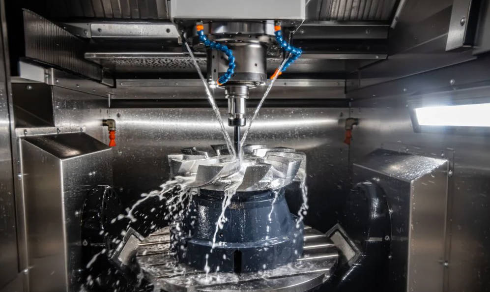
Table of Contents
- What Exactly is Surface Finish in CNC Machining?
- Why is Surface Finish a Critical Specification for CNC Parts?
- What Key Factors Influence Surface Finish During Machining?
- How Do You Achieve a Desired Surface Finish? In-Process vs. Post-Processing
- The Balancing Act: Surface Finish vs. Cost and Lead Time
- Conclusion: Making Informed Decisions About Surface Finish
What Exactly is Surface Finish in CNC Machining?
When we talk about surface finish in the context of CNC machining, we are referring to the nature of a part’s surface, defined by its collective texture characteristics. It is not just about whether a part *feels* smooth or rough; it’s a quantifiable measure of the fine-scale variations on the surface created by the machining process. Every cutting, milling, or turning operation leaves a microscopic pattern of peaks and valleys on the material. Surface finish, also known as surface texture or surface topography, is the measurement of these deviations from an ideal, perfectly flat surface.
Decoding Surface Texture: Roughness, Waviness, and Lay
To fully grasp surface finish, it’s essential to understand its three primary components:
- Roughness: This refers to the finest, high-frequency irregularities on a surface, essentially the microscopic peaks and valleys left by the cutting tool. It’s the most commonly discussed aspect of surface finish and is often measured in micrometers (µm) or microinches (µin). Think of these as the tiny scratches or tool marks you might see under magnification.
- Waviness: This describes the more widely spaced, lower-frequency variations on a surface. Waviness can be caused by machine deflection, vibration (chatter), or heat treatment. Imagine it as a series of gentle hills and valleys across the surface, upon which the smaller roughness peaks and valleys sit.
- Lay: This is the direction of the predominant surface pattern, which is typically determined by the machining method used. For example, a turned part will have a circumferential lay, while a milled surface will have a linear or arc-shaped lay. The lay can affect how a part reflects light, retains lubricant, or wears against a mating surface.
How is Surface Finish Measured? Understanding Ra, Rz, and More
Engineers and machinists use specific parameters to communicate and verify surface finish requirements. The most common parameter is Ra (Roughness Average). It represents the arithmetic average of the absolute values of the profile height deviations from the mean line, measured within a specific sampling length. In simpler terms, it’s the average height of the microscopic peaks and valleys. While Ra is a good general indicator, it can be misleading, as different surface profiles can have the same Ra value.
For more critical applications, other parameters are used:
- Rz (Mean Roughness Depth): Rz calculates the average of the five largest consecutive peak-to-valley differences within five sampling lengths. It is more sensitive to occasional high peaks or deep scratches than Ra, making it useful for applications like seals where a single deep flaw could cause a failure.
- Rmax (Maximum Roughness Depth): This measures the single largest peak-to-valley distance within the entire evaluation length. It’s used for the most critical applications where any single surface imperfection is unacceptable.
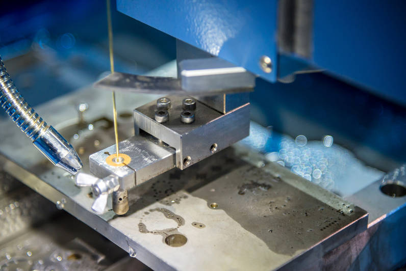
These measurements are typically taken using a highly sensitive instrument called a profilometer or a surface roughness tester, which drags a fine stylus across the surface to record its topography.
Why is Surface Finish a Critical Specification for CNC Parts?
The surface finish of a CNC machined part is far from just a cosmetic detail; it is a fundamental engineering property that directly dictates how the part will behave in its intended application. A poorly chosen surface finish can lead to premature failure, inefficiency, and compromised performance, while an overly specified finish can needlessly inflate costs and production time. The effects are multifaceted, touching on everything from mechanical function to chemical resistance.
Impact on Functional Performance: Friction, Wear, and Fatigue
The functional implications of surface finish are profound, especially for moving or mating parts. A rougher surface has more peaks (asperities) that can create friction, generate heat, and act as stress concentration points. This leads to accelerated wear and a reduced fatigue life. Conversely, a smoother surface finish on components like bearings, shafts, and gear teeth minimizes friction, allows for better lubrication film distribution, and significantly extends the part’s operational lifespan. For parts under cyclical loading, a smooth surface free of microscopic scratches can prevent the initiation of fatigue cracks, which is critical for safety and reliability.
Aesthetic and Cosmetic Appeal
For many consumer products and visible components, the look and feel are paramount. The surface finish directly controls the part’s visual quality. A fine, uniform finish can communicate quality and precision, while a rough or inconsistent finish can make a high-quality part look cheap. Different finishes can be specified to achieve various effects, from a highly reflective, mirror-like polish to a non-reflective, matte texture created by bead blasting. The direction of the lay also affects how light reflects off the surface, influencing the part’s final appearance.
Corrosion Resistance and Sealing Capabilities
Surface texture plays a significant role in a part’s interaction with its environment. Rough surfaces have a greater total surface area and can trap contaminants and moisture in their microscopic valleys, creating ideal sites for corrosion to begin. A smoother surface is easier to clean and less prone to rust and other forms of chemical attack. For applications involving seals and gaskets, surface finish is absolutely critical. If the surface is too rough, it can create leak paths under the seal. If it’s too smooth, it may not provide enough “bite” for certain types of gaskets. Therefore, a specific, controlled surface finish is often required to ensure a perfect, leak-proof seal.
What Key Factors Influence Surface Finish During Machining?
Achieving a specific surface finish is not an accident; it’s the direct result of carefully controlling numerous variables in the CNC machining process. Understanding these factors is key for both designers specifying a finish and machinists tasked with producing it. The final surface is a complex interplay between machining parameters, tooling, machine stability, and the material itself.
Machining Parameters: The Trio of Speed, Feed, and Depth of Cut
The “big three” of machining parameters have the most immediate impact on surface finish:
- Feed Rate: This is arguably the most significant factor. The feed rate is the distance the cutting tool travels per revolution of the spindle or workpiece. A slower feed rate means the tool passes over the material more frequently for a given area, creating smaller, more closely spaced tool marks (cusps), resulting in a smoother finish (lower Ra).
- Cutting Speed: This is the speed at which the workpiece surface passes the cutting edge of the tool. A higher cutting speed generally leads to a better surface finish, up to a certain point. It helps prevent the formation of a “built-up edge” (BUE) on the tool, where workpiece material welds itself to the cutting edge, which would otherwise mar the surface.
- Depth of Cut: This refers to how deep the tool cuts into the material. For finishing passes, a very shallow depth of cut is used. This minimizes cutting forces, reduces tool deflection, and lowers vibration, all of which contribute to a superior surface finish.
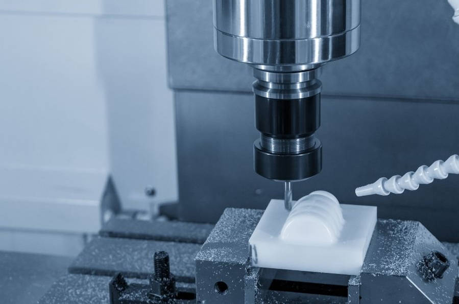
The Role of Cutting Tools: Geometry, Material, and Wear
The cutting tool is the direct interface with the workpiece, and its condition is paramount. A sharp, high-quality cutting tool is essential for shearing material cleanly. A dull or chipped tool will tear or plow through the material, smearing it and creating a rough, poor-quality surface. Tool geometry is also critical; a larger nose radius on the cutting insert will produce a smoother finish for a given feed rate because it creates wider, shallower cusps. The tool’s material and coating must also be appropriate for the workpiece material to resist wear and prevent chemical reactions that degrade the surface.
Machine Tool Rigidity and Vibration
The stability of the entire machining system—from the machine frame to the spindle and tool holder—is crucial. Any lack of rigidity can lead to vibration, or “chatter,” during cutting. Chatter is a self-excited vibration between the tool and the workpiece that leaves a distinctive, wavy pattern on the surface, drastically degrading the finish. A rigid, well-maintained machine, along with a secure workholding setup and a balanced tool holder, is necessary to minimize vibration and achieve a high-quality surface.
Workpiece Material Properties
The material being machined has its own inherent properties that affect the achievable surface finish. Softer, more ductile materials like aluminum or low-carbon steel can be “gummy” and are more prone to developing a built-up edge, which can be challenging. Harder materials like hardened steel or titanium can be machined to very fine finishes but cause rapid tool wear. The material’s grain structure and any included impurities can also introduce inconsistencies in the final surface.
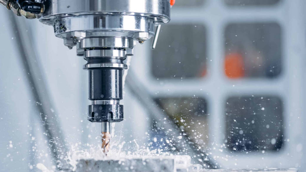
The Impact of Coolant and Lubrication
The use of cutting fluid (coolant) serves two primary purposes that directly benefit surface finish. First, it lubricates the cutting zone, reducing friction between the tool and the workpiece and helping to prevent the formation of a built-up edge. Second, it cools the workpiece and tool, preventing thermal expansion and damage that can degrade the surface and reduce tool life. A steady, high-pressure flood of clean coolant is often essential for achieving the best possible “as-machined” finish.
How Do You Achieve a Desired Surface Finish? In-Process vs. Post-Processing
Once a target surface finish is specified, there are two primary routes to achieve it: directly through the machining process itself (in-process) or through secondary operations after the main machining is complete (post-processing). The choice depends on the required finish level, part geometry, material, and cost considerations.
In-Process Techniques for a Superior “As-Machined” Finish
Achieving a good “as-machined” finish is often the most cost-effective method. This involves optimizing the factors discussed previously to produce the desired surface directly off the CNC machine. The key is to separate roughing and finishing operations. A roughing pass is performed first to remove the bulk of the material quickly, with a high feed rate and deep cut. This is followed by a separate finishing pass, which is characterized by a very shallow depth of cut, a slow feed rate, and often a higher spindle speed. Using a new or dedicated sharp tool with the correct geometry (e.g., a large nose radius) for the finishing pass is critical for getting a low Ra value without secondary steps.
Common Post-Processing Treatments for Surface Refinement
When the required surface finish is finer than what can be economically achieved through machining alone, or when specific surface properties are needed, post-processing treatments are employed. These secondary operations can smooth out the tool marks left by machining and create a wide variety of textures and finishes.
| Process | Description | Typical Ra Achieved | Primary Use Case |
|---|---|---|---|
| Grinding | Uses a rotating abrasive wheel to remove tiny amounts of material, producing a very precise and fine finish. | 0.1 – 0.8 µm (4 – 32 µin) | Hardened materials, high-precision shafts, bearing races. |
| Polishing/Lapping | Uses progressively finer abrasives on a soft pad or slurry to create a smooth, reflective, mirror-like surface. | < 0.1 µm (< 4 µin) | Optical components, molds, aesthetic showpieces. |
| Bead Blasting | Propels fine glass beads at the surface, removing tool marks and creating a uniform, non-directional, matte finish. | 1.6 – 6.3 µm (63 – 250 µin) | Aesthetic parts, reducing glare, creating a textured grip. |
| Anodizing | An electrochemical process for aluminum that creates a hard, durable, corrosion-resistant oxide layer. Can be dyed various colors. | Slightly increases roughness but provides a uniform finish. | Protective and cosmetic finishes for aluminum parts. |
| Tumbling/Vibratory Finishing | Places parts in a tumbler with abrasive media to deburr edges and smooth surfaces in bulk. | 0.8 – 3.2 µm (32 – 125 µin) | Cost-effective deburring and finishing for large batches of small parts. |
The Balancing Act: Surface Finish vs. Cost and Lead Time
One of the most important lessons in engineering design and manufacturing is that higher performance almost always comes at a higher cost. This principle is especially true for surface finish. Specifying a finish that is smoother than necessary is one of the most common ways to unintentionally drive up the cost and lead time of a CNC machined part.
Understanding the Exponential Cost-Finish Relationship
The relationship between surface finish and cost is not linear; it is exponential. A standard machined finish (e.g., Ra 3.2 µm / 125 µin) is relatively quick and inexpensive to produce. Halving that roughness to Ra 1.6 µm (63 µin) requires a slower finishing pass, which increases machine time and cost. Halving it again to Ra 0.8 µm (32 µin) requires even slower speeds and potentially special tooling, further increasing the cost. Achieving a mirror polish (Ra < 0.1 µm / 4 µin) requires multiple, time-consuming post-processing steps like grinding and lapping, which can make the part many times more expensive than one with a standard finish. This is because each incremental improvement in finish requires significantly more time, care, and often manual labor or specialized equipment.
How to Specify the Right Surface Finish for Your Project
The key to cost-effective design is to specify the roughest acceptable surface finish that still meets all the functional and aesthetic requirements of the part. Do not default to a smooth finish “just in case.”
- Analyze the Function: Is the surface a mating face, a bearing race, or a sealing surface? If so, a specific, fine finish is required. Is it a non-critical internal feature or a clearance hole? A standard, as-machined finish is likely sufficient.
- Consider the Aesthetics: If the part is a visible consumer-facing component, aesthetics are important. But even then, consider if a uniform bead blast is a more cost-effective option than a fine-ground finish.
- Consult Surface Finish Charts: Use standard charts that correlate Ra values with different manufacturing processes. This helps you understand what is practical and economical to achieve. A standard “as-machined” finish is often Ra 3.2 µm (125 µin). A fine machined finish is around Ra 1.6 µm (63 µin), and anything smoother usually requires post-processing.
- Communicate Clearly: Use standard symbols and Ra/Rz values on your engineering drawings to clearly communicate requirements to the machine shop. Avoid vague terms like “smooth finish.”
Conclusion: Making Informed Decisions About Surface Finish
Surface finish is an integral design parameter in CNC machining that profoundly influences a part’s function, appearance, lifespan, and, most critically, its cost. It is not merely a measure of smoothness but a complex feature determined by a host of factors, from machine parameters and tooling to post-processing treatments. The primary takeaway for any designer, engineer, or procurement professional is that smoother is not always better. By understanding the direct effects of surface finish on performance and the exponential impact it has on cost, you can make informed, deliberate choices. Specifying the appropriate finish—one that meets all necessary requirements without being excessive—is a hallmark of efficient design and smart manufacturing, ensuring you get the performance you need without paying for a level of precision you don’t.
CNC surface finish, surface roughness, how surface finish affects cnc parts, CNC machined parts, what is surface finish Ra, machining surface finish, factors affecting surface finish in cnc machining, cost of cnc surface finish, how to measure surface roughness, post-processing for better surface finish, CNC surface finish chart, surface texture, Ra vs Rz