In the modern landscape of high-precision manufacturing, the difference between a failed prototype and a flawless component often comes down to data. While the physical cutting tools of a CNC machine are impressive, the true “brain” of the operation lies in the digital workflow that precedes the first cut.
For engineers, product designers, and procurement managers seeking a CNC machining service, understanding the interplay between CAD (Computer-Aided Design), CAM (Computer-Aided Manufacturing), and CNC (Computer Numerical Control) is essential. This integrated workflow is what allows us to turn a digital concept into a physical reality with micron-level accuracy.
In this guide, we will demystify the “Holy Trinity” of manufacturing, explaining how we utilize your digital files to ensure speed, precision, and cost-efficiency.
The Digital Trinity: CAD, CAM, and CNC Defined
Before diving into the workflow, it is important to clarify the distinct roles of these three technologies.
- CAD (The Blueprint): This is the creative design phase where the geometry of the part is defined in 3D space.
- CAM (The Strategy): This is the process where manufacturing engineers program how the machine will make the part (tool selection, speeds, and pathing).
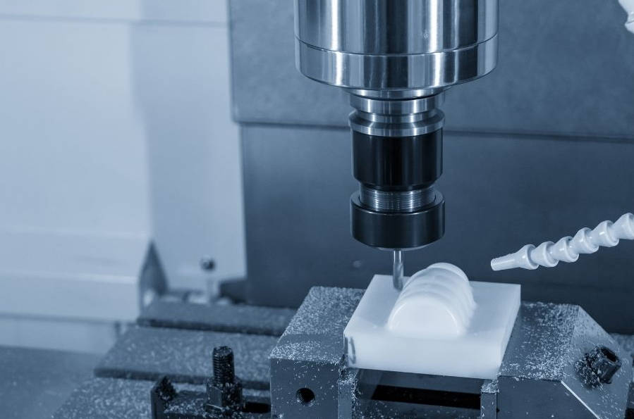
- CNC (The Execution): This is the automated machine that reads the code and physically removes material.
Google Snippet Takeaway: CAD creates the digital shape, CAM translates that shape into machine instructions (G-Code), and CNC executes those instructions to cut the physical part.
Part I: The Role of CAD – Creating the Digital Blueprint
Every successful CNC project begins with a 3D CAD model. In the past, manufacturers relied on 2D hand-drawn blueprints. Today, 3D CAD files are the non-negotiable standard for CNC machining services.
Why 3D Models are Essential for CNC
Unlike a human machinist who can look at a 2D drawing and “interpret” the shape, a CNC machine requires precise mathematical coordinates to function.
A 3D CAD model (created in software like SolidWorks, AutoCAD, or Fusion 360) defines the part as a solid object with volume, surface area, and complex curves. This “solid data” allows our CAM software to recognize features like pockets, holes, and chamfers automatically.
The Best File Formats for CNC Machining
Not all 3D files are created equal. Clients often ask: “Can I send an STL file?” While STL files are perfect for 3D printing, they are poor choices for CNC machining because they are made of triangles (mesh) rather than smooth curves.
For the highest quality results, we recommend STEP or IGES files.
File Format Compatibility Table
| File Extension | Format Name | CNC Suitability | Why? |
| .STEP / .STP | Standard for the Exchange of Product Data | Excellent (Industry Standard) | Preserves high-fidelity 3D geometry and can be opened by any CAM software. |
| .IGES / .IGS | Initial Graphics Exchange Specification | Good | An older standard, good for surfaces, but sometimes loses solid body data. |
| .X_T | Parasolid | Excellent | The native kernel for many CAD programs; very stable. |
| .STL | Stereolithography | Poor | Made of mesh triangles. Hard to machine smooth curves. Use only for 3D printing. |
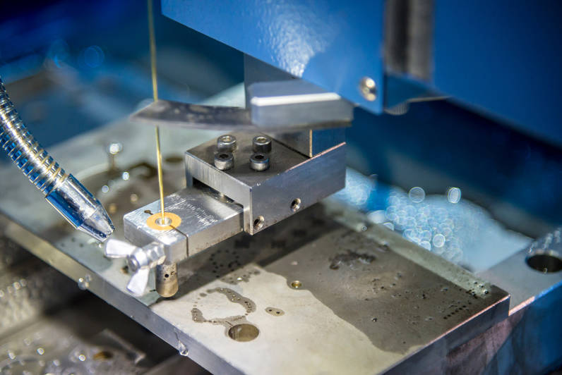
| .DXF / .DWG | Drawing Exchange Format | Limited | Useful for 2D cutting (Laser/Waterjet) but insufficient for 3-axis milling. |
The Role of 2D Drawings (PDF)
If 3D files are so important, why do we still ask for 2D PDF drawings?
While the 3D CAD file provides the shape, the 2D drawing provides the information. The CAD file does not tell the machinist:
- Which tolerances are critical (e.g., +/- 0.005mm).
- Which surfaces need a specific finish (e.g., Anodized or Polished).
- Which holes need to be threaded (tapped).
Pro Tip: To expedite your CNC machining quote, always submit a 3D STEP file for the geometry and a 2D PDF for the tolerances and thread specifications.
Part II: The Role of CAM – The Bridge Between Design and Reality
This is the stage where the “magic” happens, and where the expertise of your manufacturing partner adds the most value. Clients often assume that we simply load the CAD file into the machine and press “Go.” In reality, CAM programming is a complex engineering task.
Developing the Machining Strategy
Once we receive your CAD file, our CAM engineers import it into software (such as Mastercam or Hypermill). Their job is to determine the most efficient way to carve your part from a raw block of material.
Key decisions made during the CAM stage include:
- Tool Selection: Choosing the right drill bits, end mills, and face mills. For example, a small radius in your design requires a small tool, which might require a slower cutting speed.
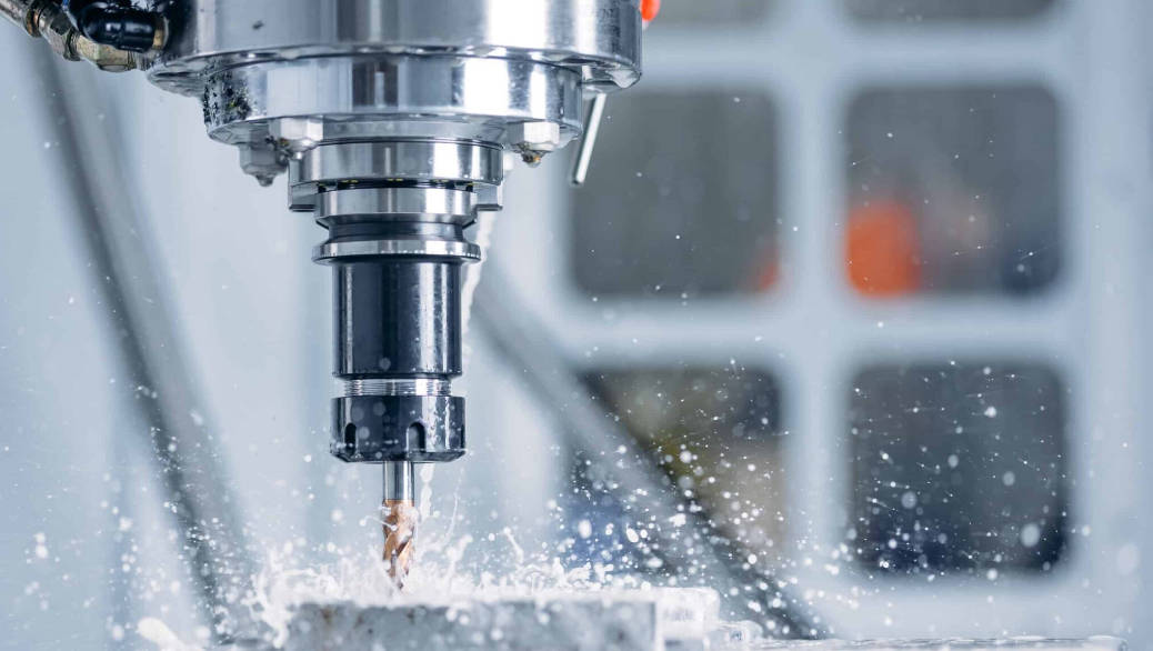
- Feeds and Speeds: Calculating how fast the spindle should spin (RPM) and how fast the tool should move across the material (Feed Rate). This calculation changes based on material (Aluminum vs. Titanium).
- Roughing vs. Finishing:
- Roughing: Removing large amounts of material quickly to get close to the final shape.
- Finishing: A slow, high-precision pass to achieve the final dimensions and smooth surface.
The “Digital Twin” Simulation
Before a single chip of metal is cut, advanced CAM software runs a full simulation. This creates a “Digital Twin” of the machining process.
Why is this important for the customer?
- Collision Detection: The software predicts if the tool will accidentally hit the clamp or the machine table.
- Error Prevention: It ensures that the programmed toolpath matches the original CAD geometry exactly.
- Cost Reduction: By optimizing the path digitally, we reduce “air cutting” (time when the tool isn’t cutting), which lowers the run time and the final price.
Part III: From G-Code to CNC – The Execution
Once the CAM strategy is finalized and simulated, the software translates these visual toolpaths into a language the machine understands: G-Code.
What is G-Code?
G-Code is the programming language used to control CNC machines. It consists of a series of alphanumeric commands that tell the machine where to move (X, Y, Z coordinates), how fast to move, and when to change tools.
For example:
- G01 X10.0 Y5.0 F100 tells the machine to move in a straight line to position X=10, Y=5 at a feed rate of 100.
- M03 S2000 tells the spindle to turn on clockwise at 2000 RPM.
While modern machines are incredibly advanced, they are blindly obedient. They will execute the G-Code exactly as written. This is why the CAD/CAM verification phase is so critical—any error in the digital design will be faithfully reproduced in hard metal.
Precision Control
Modern CNC machines use this G-Code to control servo motors with incredible accuracy. Through the integration of CAD/CAM data, our machines can achieve:
- Positional Accuracy: +/- 0.01mm (0.0004″).
- Repeatability: Ensuring the 1,000th part is identical to the 1st part.
Part IV: Why This Integration Matters to You (The Customer)
Why should a customer care about how CAD and CAM interact? Because a seamless digital workflow directly impacts your project’s cost, lead time, and quality.
1. Speed and Efficiency
In the era of manual machining, a machinist had to stop and measure the part constantly. With an integrated CAD/CAM workflow, the machine runs continuously.
Automated toolpaths significantly reduce cycle times, leading to faster delivery of your parts.
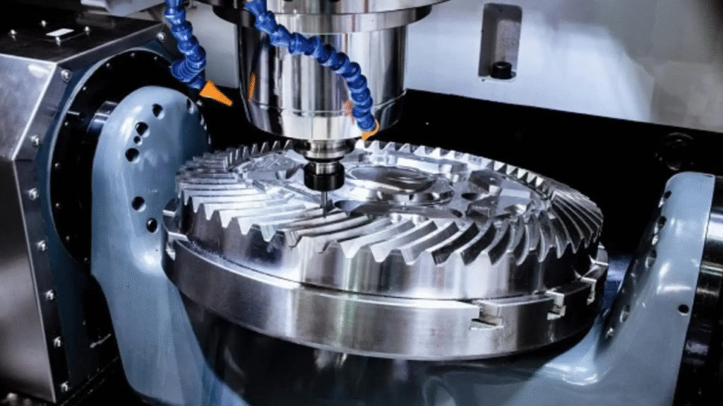
2. Complex Geometries (5-Axis Machining)
Manual machining is limited to simple straight lines and circles. However, with CAD/CAM driving a 5-axis CNC machine, we can produce organic shapes, aerospace impellers, and medical implants that would be impossible to manufacture by hand.
The CAM software calculates complex vectors to keep the tool perpendicular to the surface at all times, creating smooth, flowing geometries.
3. Consistency and Scalability
Because the process is driven by digital code, it is perfectly repeatable. If you order a prototype today and come back six months later for a production run of 5,000 units, we simply reload the CAM program. The parts will be identical.
4. Cost Reduction via Optimization
A skilled CAM engineer uses the software to find cost-saving opportunities.
- Nesting: Arranging multiple parts on a single sheet of material to reduce waste.
- Adaptive Clearing: A high-speed milling strategy that maintains constant tool engagement, extending tool life and reducing machine time costs.
Comparison: Manual vs. CAD/CAM CNC Machining
| Feature | Manual Machining | CAD/CAM CNC Machining |
| Input Data | Printed Drawings | 3D Digital Models |
| Complexity | Simple, Linear Shapes | Complex, Organic 3D Shapes |
| Speed | Slow, Labor Intensive | Fast, Automated |
| Accuracy | Dependent on Operator Skill | Dependent on Machine Calibration |
| Scalability | Low | High (Mass Production Ready) |
Part V: FAQ – Common Questions About Files & Process
To help you prepare your next project, here are answers to the most common questions we receive regarding CAD and CAM data.
Q: I only have a physical part, no CAD file. Can you still machine it?
A: Directly, no. The machine needs digital data. However, we can offer Reverse Engineering services. We can 3D scan your physical part to create a new 3D CAD model, which can then be used for machining.
Q: Do I need to program the CAM toolpaths myself?
A: No. As your CNC machining service provider, that is our responsibility. You only need to provide the design (CAD). Our engineers handle the CAM programming to ensure the part is manufactured safely and efficiently.
Q: Can you work with a 2D DXF file for CNC milling?
A: For simple plates with holes, yes. However, for most milled parts, a DXF is insufficient because it lacks depth information (Z-axis). Converting a 2D DXF into a 3D part takes extra time. Providing a STEP file is always faster and cheaper.
Q: What is “Model-Based Definition” (MBD)?
A: MBD is a modern practice where tolerances and manufacturing notes are embedded directly into the 3D CAD file, eliminating the need for a separate 2D PDF drawing. We are fully equipped to handle MBD workflows.
VI. Conclusion: The Secret to Perfect Parts
The journey from a concept in your mind to a precision metal part in your hand is powered by the seamless integration of CAD and CAM.
- CAD ensures your design intent is captured geometrically.
- CAM calculates the most efficient, safe, and precise path to cut that geometry.
- CNC machines execute that path with superhuman consistency.
However, software is only a tool. The “secret sauce” to perfect parts lies in the expertise of the engineers managing this workflow. At [Your Company Name], our team verifies every CAD file and optimizes every CAM path to ensure you get the highest quality parts at the best possible price.
Ready to Manufacture?
Do you have a design ready for production? Don’t let your digital files sit idle.
Upload your STEP files to [Your Company Name] today. Our engineering team will review your design, optimize the CAM strategy, and provide a free quote and DFM analysis within 24 hours.
TDK (Title, Description, Keywords)
Title Tag:
How CAD and CAM Work with CNC Machining for Perfect Parts | The Full Guide
Meta Description:
Understand the workflow from CAD design to CAM programming and CNC execution. Learn why STEP files are essential and how digital integration ensures precision in CNC machining services.
Keywords:
CNC machining service, CAD and CAM explained, CAD to CNC workflow, G-Code for CNC, STEP vs STL for machining, CNC programming process, 5-axis CAM, precision manufacturing.