I. Introduction
In the world of modern manufacturing, Computer Numerical Control (CNC) turning stands as a cornerstone technology. This subtractive manufacturing process is renowned for its ability to produce complex cylindrical parts with exceptional precision and repeatability. From the intricate components in an airplane’s landing gear to the life-saving devices used in the medical field, the impact of CNC turning is everywhere. It is a vital process for creating parts that are not only functional but also perfectly formed to meet exacting specifications.
The purpose of this comprehensive guide is to demystify the key design considerations for CNC turned parts. We aim to address the most common questions and challenges faced by designers, engineers, and product developers who utilize CNC turning services. By understanding the fundamentals of tolerances, the nuances of wall thickness, and the best practices for designing threads, you can significantly improve the manufacturability, quality, and cost-effectiveness of your components.
This article is for anyone involved in the product development lifecycle—from seasoned mechanical engineers looking to refine their Design for Manufacturing (DFM) skills to entrepreneurs and innovators seeking to bring their first physical product to life. Whether you are designing for a one-off prototype or a high-volume production run, the principles discussed here will empower you to create optimized designs that translate seamlessly from a CAD file to a finished, high-quality part.
II. Understanding CNC Turning
What is CNC Turning?
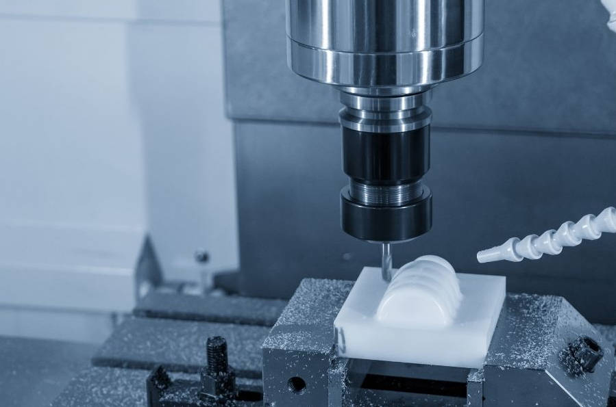
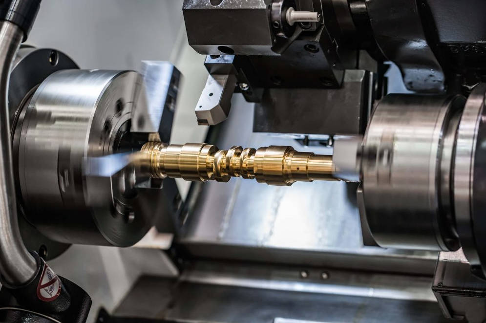
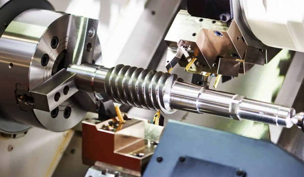
CNC turning is a subtractive manufacturing process that involves holding a workpiece in a rotating chuck and feeding a cutting tool along it to remove material and create a cylindrical part. The entire operation is controlled by a computer program, which dictates the tool’s movements, the spindle’s speed, and the feed rate with incredible precision. The primary machine used is a lathe, and the process is ideal for creating parts with rotational symmetry, such as shafts, pins, rings, and fittings.
The process begins with a digital 3D model (CAD file) of the part. This model is then converted into a set of instructions, known as G-code, by CAM (Computer-Aided Manufacturing) software. The G-code is loaded into the CNC lathe’s controller, which then automates the machining process. A cylindrical stock material, such as a metal rod or plastic bar, is secured in the lathe’s chuck. As the chuck spins the material at high speeds (RPM), a stationary or moving cutting tool is brought into contact with it. The tool carves away material according to the programmed path, shaping the final component. Modern CNC turning centers can also incorporate live tooling, which allows for secondary operations like drilling, milling, and tapping to be performed in the same setup, further enhancing efficiency and accuracy.
Common Applications and Industries
The precision, efficiency, and versatility of CNC turning make it indispensable across a vast range of industries:
- Aerospace: This sector demands the highest level of precision and material integrity. CNC turning is used to produce critical components like turbine shafts, engine mounts, hydraulic fittings, and landing gear components, where failure is not an option.
- Automotive: From engine components like pistons and camshafts to transmission shafts and suspension parts, CNC turning is fundamental to the automotive industry. It provides the speed and repeatability needed for mass production while meeting strict quality standards.
- Medical: In the medical field, CNC turning is used to create surgical instruments, medical implants (such as bone screws and spinal fusion cages), and components for diagnostic equipment. Biocompatible materials like titanium and medical-grade stainless steel are commonly used.
- Electronics: The electronics industry relies on CNC turning for producing connectors, sockets, housings, and heat sinks with tight tolerances required for miniature and high-performance devices.
- Defense: CNC turning produces a wide array of components for military applications, including munitions parts, firearm barrels, and guidance system components, where ruggedness and reliability are paramount.
Benefits of CNC Turning
Choosing CNC turning for your manufacturing needs offers several significant advantages:
- Exceptional Precision and Accuracy: CNC turning machines can achieve extremely tight tolerances, often as fine as ±0.005 mm (±0.0002 inches), ensuring parts meet exact specifications. This level of accuracy is repeatable across thousands of units.
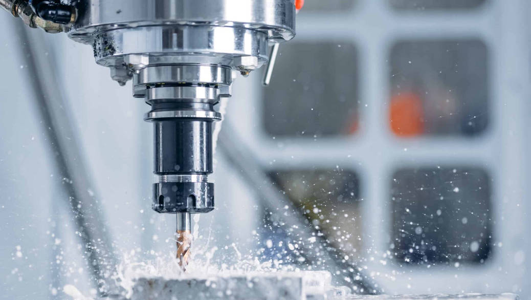
- High Efficiency and Speed: Once programmed, a CNC lathe can operate continuously with minimal human intervention, making it highly efficient for both rapid prototyping and large-scale production runs. The automated process drastically reduces cycle times compared to manual machining.
- Material Versatility: The process is compatible with a wide array of materials, from soft plastics and aluminum to hardened steels and exotic alloys like Inconel and titanium.
- Complex Geometries: Modern multi-axis CNC turning centers can produce parts with complex geometries, including intricate contours, grooves, and threads, in a single setup.
- Superb Surface Finishes: CNC turning can produce parts with very smooth surface finishes (low Ra values), often eliminating the need for secondary polishing or grinding operations.
III. Key Design Considerations for CNC Turned Parts
Optimizing your part design for CNC turning is the single most effective way to reduce costs, shorten lead times, and improve the final quality of your product. This section delves into the three most critical design elements: tolerances, wall thickness, and threads.
A. Tolerances
Explanation of Tolerances in CNC Turning
In manufacturing, a tolerance is the permissible limit or limits of variation in a physical dimension of a part. It defines the acceptable range between the maximum and minimum allowable size for a specific feature. For example, a shaft with a diameter specified as 20 mm ±0.05 mm means the final part is acceptable if its diameter measures anywhere between 19.95 mm and 20.05 mm. Tolerances are crucial in mechanical design because they ensure the proper fit, form, and function of parts in an assembly.
In CNC turning, tolerances are controlled by the precision of the machine, the sharpness of the cutting tool, the material’s properties, and the skill of the machinist/programmer. Achieving tighter (smaller) tolerances requires more careful setups, slower machining speeds, more frequent tool changes, and potentially secondary processes like grinding, all of which add to the production time and cost.
Standard Tolerance Ranges and Their Impact on Cost
Understanding the relationship between tolerance and cost is essential for economical design. CNC turning providers typically offer a standard tolerance range that can be achieved without special effort. Specifying tolerances tighter than the standard will invariably increase the price.
A common mistake in design is to apply a blanket tight tolerance to every feature on a part. This is unnecessary and expensive. The best practice is to identify the critical features that require tight tolerances for functionality (e.g., a bearing fit) and assign a more relaxed, standard tolerance to non-critical features.
Here’s a general guide to how tolerances can affect cost:
| Tolerance Type | Typical Range (for Metals) | Relative Cost Increase (Approx.) | Notes |
|---|---|---|---|
| Standard | ±0.1 mm (±0.004 in) | Baseline (1x) | Achievable with standard setups and tooling. Ideal for non-critical features. |
| Fine / Tight | ±0.025 mm (±0.001 in) | 1.5x – 3x | Requires more precise machine calibration, slower speeds, and in-process checks. |
| Extra Fine | ±0.01 mm (±0.0004 in) | 4x – 10x+ | Often requires specialized tooling, climate-controlled environments, and post-machining grinding. |
Tips for Specifying Tolerances Effectively
- Analyze Functionality: Before assigning any tolerance, ask: “What is the function of this feature?” Does it mate with another part? Does it need to be a specific size for clearance? This analysis will determine which features are critical.
- Use Standard Tolerances by Default: Apply a standard tolerance (e.g., ±0.1 mm) as the default for your entire part and only specify tighter tolerances on an exception basis for critical features.
- Consult Your CNC Service Provider: Communicate with your manufacturing partner early in the design process. They can provide valuable feedback on what tolerances are reasonably achievable for your chosen material and geometry, and suggest design modifications for cost savings.
- Consider GD&T: For complex parts, use Geometric Dimensioning and Tolerancing (GD&T) to specify tolerances for features relative to each other (e.g., perpendicularity, concentricity). This can often be more functional and less restrictive than simple bilateral tolerances.
Common Mistakes to Avoid
- Over-tolerancing: The most common mistake is applying unnecessarily tight tolerances across an entire part. This is the fastest way to inflate manufacturing costs without adding any functional value.
- Ignoring Material Properties: Different materials behave differently during machining. For example, plastics have a higher coefficient of thermal expansion and can be less rigid, making it harder to hold very tight tolerances compared to steel.
- Conflicting Tolerances: Ensure that the tolerances on your drawing do not conflict with each other. A tolerance stack-up analysis can be helpful for complex assemblies.
B. Wall Thickness
Importance of Appropriate Wall Thickness
Wall thickness is a critical design parameter for CNC turned parts, directly impacting their structural integrity, stability during machining, and overall weight. A well-designed part has walls that are thick enough to withstand the forces of both the machining process and its end-use application, but not so thick that they add unnecessary weight and material cost.
The primary challenge with thin walls in CNC turning is vibration, also known as “chatter.” When a cutting tool engages a thin, unsupported wall, the wall can deflect or vibrate, leading to a poor surface finish, dimensional inaccuracies, and even tool breakage.
Recommended Minimum and Maximum Wall Thicknesses
The minimum achievable wall thickness depends heavily on the material’s rigidity, the part’s geometry, and the machining setup. While it’s possible to machine extremely thin walls, it requires special techniques and adds significant cost.
As a general design guideline, the recommended minimum wall thickness for CNC turned metal parts is 0.8 mm (0.030 inches), and for plastics, it is 1.5 mm (0.060 inches). Walls thinner than this are possible but should be discussed with your manufacturer as they may require special support or slower machining, increasing costs.
Here is a table of general recommendations for common materials:
| Material | Recommended Minimum Wall Thickness | Key Considerations |
|---|---|---|
| Aluminum (e.g., 6061) | 0.8 mm (0.030 in) | Good machinability but prone to warping if internal stresses are not managed. |
| Stainless Steel (e.g., 304, 316) | 1.0 mm (0.040 in) | Strong and rigid, but work-hardens. Requires robust tooling and setup to prevent chatter. |
| Mild/Carbon Steel | 1.0 mm (0.040 in) | Generally stable and machines well, allowing for reasonably thin walls. |
| Brass | 0.7 mm (0.028 in) | Excellent machinability allows for very thin walls, but it’s a softer material. |
| Plastics (e.g., Delrin, PEEK) | 1.5 mm (0.060 in) | Lower rigidity and higher thermal expansion. Prone to melting and warping with thin walls. |
Balancing Strength, Weight, and Machinability
The ideal design strikes a balance between these three factors:
- Strength: The wall must be thick enough to handle the mechanical loads and stresses it will experience in its application. Use Finite Element Analysis (FEA) software to simulate these loads and validate your design.
- Weight: In many applications (especially aerospace and automotive), minimizing weight is critical. Design walls to be as thin as functionally possible. Consider adding ribs or gussets to increase stiffness in specific areas rather than making the entire wall thicker.
- Machinability: Very thin walls are difficult to machine accurately. A slightly thicker wall might allow for faster, more stable machining, potentially offsetting the cost of the extra material. Uniform wall thickness is also highly desirable as it helps to minimize warping and internal stress.
Common Issues with Improper Wall Thickness
- Warping: When significant amounts of material are removed, internal stresses within the material can be released, causing the part to warp. This is especially problematic in parts with non-uniform wall thicknesses.
- Tool Deflection: When machining a thin wall, the force of the cutting tool can cause the wall to push away, resulting in an inaccurate final dimension.
- Poor Surface Finish: Vibration (chatter) is the enemy of a good surface finish. It leaves a wavy, uneven pattern on the part surface.
- Part Breakage: In extreme cases, a wall that is too thin for the machining forces can simply break off during the operation.
C. Threads
Overview of Threading in CNC Turning
Threads are helical ridges used to convert rotational motion into linear motion or to fasten components together. In CNC turning, threads can be cut on both the external and internal surfaces of a part with very high precision. The CNC machine controls the synchronized movement of the rotating spindle and the linear motion of the threading tool to generate the precise helical path required.
Types of Threads
Threads are defined by various standards, and it’s crucial to specify the correct one on your drawing. The main types include:
- Internal vs. External: External threads are cut on the outside of a cylinder (like a bolt), while internal threads are cut on the inside of a hole (like a nut).
- Metric vs. Imperial:
- Metric Threads (M series): The global standard, defined by the ISO. They are specified by their nominal diameter and pitch (the distance between adjacent threads) in millimeters. For example,
M10 x 1.5indicates a 10 mm diameter thread with a 1.5 mm pitch. - Imperial Threads (Unified Thread Standard – UTS): Commonly used in the United States. They are categorized into UNC (Unified National Coarse), UNF (Unified National Fine), and UNEF (Unified National Extra Fine). They are specified by their diameter (in inches or a number gauge for small sizes) and the number of threads per inch (TPI). For example,
1/4"-20 UNCindicates a 0.25-inch diameter bolt with 20 threads per inch, of the coarse series.
- Metric Threads (M series): The global standard, defined by the ISO. They are specified by their nominal diameter and pitch (the distance between adjacent threads) in millimeters. For example,
Best Practices for Designing Threads
Properly designing threads for manufacturability can prevent a host of problems during production.
- Avoid Bottoming Out Threads: Never design a thread that extends all the way to the bottom of a blind (closed) hole. The threading tool needs space to stop and retract. Always design the drilled hole to be deeper than the required thread length. A good rule of thumb is to make the unthreaded portion at the bottom of the hole at least 3-5 pitches long.
- Incorporate Thread Relief: For external threads that end at a shoulder (a step-up in diameter), it is highly recommended to include a thread relief groove (an undercut). This small groove at the end of the thread allows the threading tool a clean exit path, ensuring a fully formed last thread and allowing a mating part to sit flush against the shoulder.
- Specify Standard Threads: Always use standard, off-the-shelf thread sizes whenever possible. Custom thread profiles require custom-ground tooling, which is extremely expensive and adds significant lead time.
- Keep Thread Length Reasonable: Very long threads, especially those with a fine pitch, can lead to increased tool wear and a higher chance of defects. A good design guideline is to keep the thread length to a maximum of 3 times the nominal diameter of the thread. For most fastening applications, a thread engagement length of 1.5 times the diameter is sufficient.
- Consider Tapped vs. Thread Milled Holes: For internal threads, tapping is the most common and cost-effective method. However, for large diameter threads or difficult-to-machine materials, thread milling can offer better quality and tool life.
Common Threading Challenges
- Tool Wear: Threading is a demanding operation that puts significant stress on the cutting tool. In hard materials, tool tips can wear quickly, leading to out-of-spec threads.
- Poor Thread Quality: Issues like burrs, torn threads, or incorrect pitch diameter can result from improper speeds and feeds, worn tooling, or a non-rigid setup.
- Chip Evacuation: In deep internal threading operations, chips can become packed inside the hole, potentially breaking the tap or damaging the threads.
IV. Material Selection for CNC Turning
The choice of material is a foundational decision that influences nearly every aspect of your project, from the part’s mechanical properties and performance to its machinability, cost, and lead time.
Common Materials Used in CNC Turning
CNC turning can be performed on a vast spectrum of materials. The most common can be grouped into metals and plastics.
- Aluminum (e.g., 6061, 7075):
- Pros: Excellent strength-to-weight ratio, good corrosion resistance, and outstanding machinability. 6061-T6 is the most popular all-around choice.
- Cons: Softer and less strong than steel. Can be prone to “gummy” machining if not handled correctly.
- Steel (e.g., 1018 Mild Steel, 4140 Alloy Steel, 12L14 Free-Machining):
- Pros: High strength, durability, and relatively low cost. A huge variety of alloys are available to suit different applications (e.g., hardness, weldability).
- Cons: Heavier than aluminum, and generally has lower corrosion resistance (requires plating or coating).
- Stainless Steel (e.g., 304, 316, 17-4 PH):
- Pros: Excellent corrosion resistance, high strength, and can be used in sterile/food-grade applications.
- Cons: More difficult and slower to machine than carbon steel due to its tendency to work-harden. This makes it more expensive.
- Brass (e.g., C360):
- Pros: Brass is arguably the easiest metal to machine, allowing for very high speeds, excellent surface finishes, and long tool life. It also has good corrosion resistance and electrical conductivity.
- Cons: Lower strength than steel and is a relatively dense, heavy material.
- Titanium (e.g., Grade 2, Grade 5/Ti 6Al-4V):
- Pros: Exceptional strength-to-weight ratio (as strong as steel at about half the weight), and superb corrosion resistance. Biocompatible.
- Cons: Very expensive and difficult to machine.
- Plastics (e.g., Delrin/Acetal, PEEK, Nylon, ABS):
- Pros: Lightweight, low cost, natural lubricity, and good chemical resistance.
- Cons: Lower strength and rigidity than metals. Prone to thermal expansion and warping, making it difficult to hold very tight tolerances.
How Material Choice Affects Design Considerations
Your material selection has a direct impact on the design rules for tolerances, wall thickness, and threading:
- Tolerances: It is easier and therefore cheaper to hold tight tolerances on materials with high dimensional stability and good machinability, like steel or brass. For plastics, which can expand with heat and absorb moisture, holding the same tight tolerances is much more challenging and costly.
- Wall Thickness: Rigid materials like steel and titanium can support thinner walls during machining than less rigid materials like aluminum or plastics.
- Threading: Free-machining materials like Brass C360 or 12L14 Steel are ideal for creating perfect threads. Tough, gummy materials like some stainless steels or copper can be challenging, increasing the risk of torn threads.
Tips for Selecting the Right Material
- Define Mechanical Requirements: Start by listing the essential properties your part needs. Does it need to be strong, hard, lightweight, or corrosion-resistant?
- Consider the Operating Environment: Will the part be exposed to high temperatures, moisture, or harsh chemicals? This will narrow down your choices significantly (e.g., stainless steel for wet environments).
- Balance Performance and Cost: Don’t over-engineer. Don’t choose an expensive material like PEEK or Titanium if a more common one like Delrin or Aluminum would suffice. Always consult a materials properties datasheet to compare candidates.
- Factor in Machinability: If you have a complex part with many features, choosing a material with good machinability can lead to significant cost savings in production time, even if the raw material is slightly more expensive.
V. Design Optimization Tips (DFM)
Design for Manufacturing (DFM) is the practice of designing parts in a way that makes them as easy and economical to manufacture as possible. Applying DFM principles to your CNC turned parts can yield dramatic cost savings.
- Simplify Geometry: Complexity drives cost. Wherever possible, simplify your design. Can a complex curve be replaced by a straight line or a simple arc? Can multiple intricate features be combined into a simpler form? Fewer machine movements mean less time and less cost.
- Incorporate Chamfers and Fillets (Radii):
- Sharp internal corners are difficult and expensive to machine. Standard cutting tools are round and will naturally leave a radius in an internal corner. Specifying a radius on all internal corners that is slightly larger than the tool’s radius will reduce machining time and cost.
- Adding chamfers or radii to external edges is also good practice. It helps to break sharp edges, which can be brittle and are a safety hazard. This is a simple operation on a CNC lathe.
- Avoid Deep Pockets and Narrow Grooves: Deep, narrow features are challenging for CNC turning. They require long, slender tools that are prone to vibration and breakage. A good rule of thumb is that a groove or pocket’s depth should not exceed 4-5 times its width. If a deep feature is necessary, consider if it can be designed with a taper to improve tool access.
- Use Standard Tool and Drill Sizes: When designing holes, try to use standard drill bit sizes. If you specify a non-standard hole size (e.g., 8.15 mm), it may require a special tool or a secondary boring operation, adding cost. Stick to standard fractional, number, or letter drill sizes.
- Design for a Single Setup: If possible, design your part so that all features can be machined from one side (in a single setup). Every time a part has to be removed, flipped, and re-fixtured, it introduces potential for error and significantly increases labor and machine time. Modern CNC turning centers with sub-spindles can automate this process, but a simpler design is always better.
VI. Common Questions and Concerns
How to balance cost and precision in CNC turning projects?
This is the central challenge in designing for manufacturing. The key is to be selective. Use a cost-benefit analysis for every tight tolerance you specify. Ask if the improved precision truly adds functional value that justifies the 2x or 3x cost increase for that feature. Communicate with your manufacturer and clearly mark the critical dimensions on your drawing. For all other non-critical features, allow them to be machined to the shop’s standard, more economical tolerance.
Addressing lead time concerns for CNC turned parts
Lead time is affected by material availability, part complexity, and the current capacity of the machine shop. To minimize lead times:
- Choose common, readily available materials.
- Simplify your design using DFM principles to reduce machining time.
- Provide a clear, accurate 2D drawing and 3D model to avoid delays caused by ambiguity.
- Discuss your timeline with your supplier upfront. For urgent needs, many shops offer expedited services for a premium.
How to ensure part quality and consistency?
Quality assurance starts with a good design and clear documentation.
- Provide a Complete Technical Drawing: Your drawing should include all dimensions, tolerances, material specifications, thread callouts, and any required surface finish or post-processing notes.
- Choose a Reputable Supplier: Select a CNC turning service provider with a proven track record and a robust quality management system (e.g., ISO 9001 certification).
- Request Inspection Reports: For critical parts, you can request first article inspection (FAI) reports or a certificate of conformance (CoC) to verify that the parts meet your specifications.
Communicating effectively with CNC turning service providers
Clear communication is vital for success. When you submit a Request for Quote (RFQ), provide as much information as possible:
- 3D CAD files (STEP or IGES format is preferred).
- A complete 2D technical drawing (PDF format).
- The material specification.
- The quantity required (and potential future quantities).
- Any required secondary finishes (e.g., anodizing, plating).
- Your desired delivery date.
Be open to feedback. A good manufacturing partner will often suggest minor design tweaks that can save you a significant amount of money. This collaborative approach leads to the best outcomes.
VII. Conclusion
Mastering the design of CNC turned parts is a journey of understanding the interplay between design intent and manufacturing reality. By focusing on the three pillars of tolerances, wall thickness, and threads, you can unlock significant improvements in the quality, cost, and delivery time of your components. Remember to apply tolerances judiciously, design walls for stability, and follow best practices for creating manufacturable threads.
Ultimately, the most successful projects are born from collaboration. Engage with your CNC service provider early and often. Leverage their expertise in materials and machining processes to refine your designs. By applying the DFM tips outlined in this guide and fostering a strong partnership with your manufacturer, you will be well-equipped to create optimized, efficient, and highly effective CNC turned parts that perfectly meet the demands of your application.